1.Product introduction ofautomatic vegetation index monitor
The vegetation index automatic monitor, also known as the shrub and grass vegetation index automatic monitoring system, is an intelligent vegetation observation device that measures the temperature of plant leaves to calculate the water shortage of plants, the strength of plant transpiration and respiration. Weak, it can also be used to observe plant growth and nutritional information.
Plant leaf temperature, diameter growth and normalized vegetation index are very important indicator parameters that reflect plant growth status.Usually, by measuring the temperature of plant leaves, we can calculate the water shortage of plants, the strength of plant transpiration and respiration, and even predict the disease status of plants.The normalized vegetation index and plant diameter growth can directly or indirectly reflect plant growth and nutritional information.
The plant growth status online monitoring system uses low-power, high-precision measurement equipment, and can use solar panels to power the equipment to achieve automatic online measurement in the field.
The online monitoring system for plant growth status can also simultaneously observe growth and meteorological factors. This not only accurately identifies the key factors affecting growth, but also brings great convenience to data processing.
2.Product features of vegetation index automatic monitor
1. Power supply system: Wind and solar complementary power supply system, AC 220V, DC 5V, 12V, solar energy, etc., selected according to user needs.
2. Reliable operation in various harsh outdoor environments, low power consumption, high stability, high precision, and can be left unattended.
3. Complete protection measures against lightning strikes and anti-interference.
4. Both hardware and software adopt modular modular open design and can be used in flexible combinations.
5. Monitoring elements can be selected according to actual needs.The modular design greatly facilitates later equipment debugging and upgrades.
6. The communication method can be selected as needed according to the transmission distance, providing a cost-effective solution.
7. The environmental WEB publishing system allows users to browse environmental station on-site environmental data at any time on the LAN and the Internet.
8. Client browsing: You can use the software client to query and collect statistics on the environmental station's on-site environment data on the LAN and the Internet.
3.Product parameters of vegetation index automatic monitor
1. Soil temperature, moisture and conductivity sensor: soil moisture parameters: range 0-100%, resolution 0.1%, accuracy 0-50% ±2%, (brown soil, 30%, 25"C), 50-100% Within ±3%, (brown soil, 60%, 25C); soil temperature parameters: range -40~80℃, resolution 0.1℃, accuracy ±0.5℃; conductivity parameters: range 0-20000us/cm, resolution 10us /cm;
2. Solar panel: 120W solar panel +12V, 60AH battery;
3. Pole: ≥2.5M, white paint;
4. Achieve real-time image collection for shrubs and grass, and support remote setting of fixed-point and fixed-frequency collection strategies;
5. Built-in automatic analysis algorithm to realize shrub and grass image preprocessing, vegetation classification and recognition, vegetation growth analysis, etc.;
6. Memory capacity: 16Mb, more than 100,000 data points;
7. Communication method: supports GPRS communication, RS232 data output, and Lora wireless communication;
8. Built-in GPS positioning function, capable of reporting geographical location information.
9. Transportation and installation fees and three-year Internet of Things fees.
4.Vegetation Index Automatic MonitorVegetation Index Monitoring Equipment Standard Operation Instructions
1. Tool preparation: slotted screwdriver, diagonal pliers, wire strippers, 6mm hexagon socket, 7mm wrench, 14mm wrench, 17mm wrench
2. Equipment accessories list: control box, 2.5m light pole, lightning rod, battery board bracket, 60W battery board*2, 60AH battery, gun camera, gun bracket, connectors
3. Step-by-step operation:
1. Battery panel bracket assembly standards and steps:
1) Accessories: 2 60W battery panels, 60AH batteries, 4 M6*20 screw nuts each, 4 flat spring washers each
2) Fix the battery board, pay attention to using flat pads and spring pads, and fix them firmly
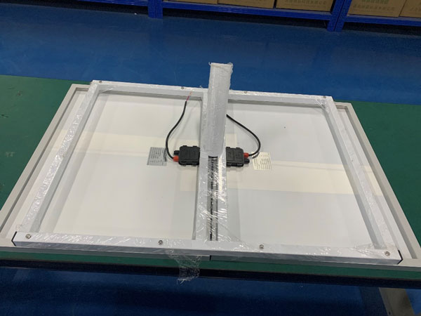
3) Connect the battery board. Note that the red wire is the positive pole and the black (blue) wire is the negative pole. The two battery boards are connected in parallel to the extension.
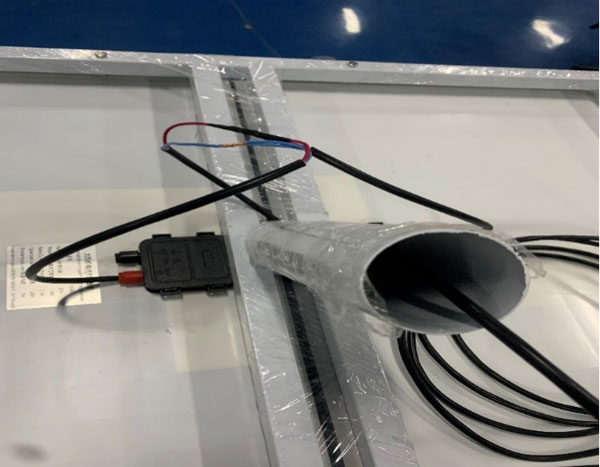
4) The assembly of the battery panel bracket is completed
4. Overall equipment assembly standards and steps:
1) Component preparation: battery panel bracket, lightning rod, control box, control box connection frame, light pole, camera, camera bracket, connectors
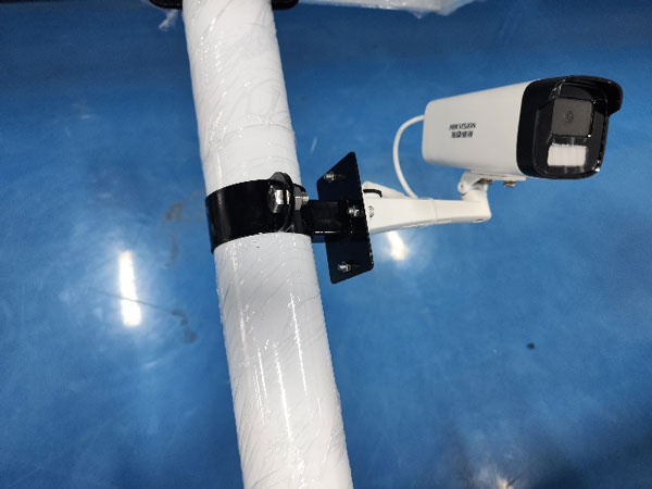
2) Install the fixed gun camera, fix the gun and the gun bracket (white), pass the gun cable into the gun bracket, connect a network cable (7m blue network cable) and power cable (DC plug cable), and then Fix it with the bolt connector (black), and leave the connector in the bolt bracket (the connector is wrapped with waterproof tape). Finally, pass the network cable and power cord into the lamp pole from the 30cm threading hole on the top of the lamp pole, and exit the control box hole (1.2m away from the base of the light pole) through the light pole, and secure the connecting piece to the light pole.
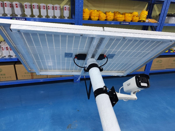
3) Install and fix the battery panel and thread it. Pass the battery panel wire through the cable entry hole at the top of the lamp pole into the lamp pole, and out of the control box outlet hole (1.2m away from the lamp pole base), and then insert the battery panel bracket into the lamp pole. Inside, fix the three screws and tighten them. Note that the battery panel faces south (based on the direction of the control box)
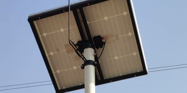
4) Install and fix the lightning rod. The lightning rod is installed and fixed on the north side of the light pole, with the pointer facing up. Be careful not to install it backwards. After installation, tighten the screws.
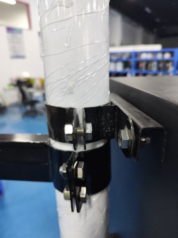
5) Install the fixed control box. First, fix the control box connectors (two) on the light pole, and adjust the corresponding position (the lower connector is fixed 1cm above the wiring hole of the light pole control box). Loosen the four screws of the hanging control box. screws, hang the control box on the connector, adjust the position, and then tighten all the fixing screws
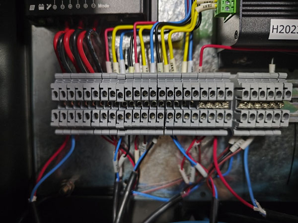
6) Wire the control box, connect the battery board wire to the battery board terminal of the controller, and connect the battery wire to the battery terminal of the controller. Be careful not to reverse the positive and negative poles; connect each sensor to the corresponding position according to the wire number or label.
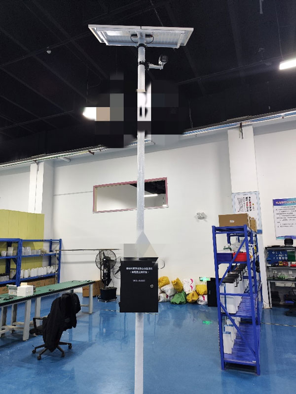
7) The equipment installation is completed (Note: The battery wire goes through the control box from the bottom of the light pole; the soil sensor wire goes through the threading hole at the bottom of the light pole into the control box, and the sensor is inserted 10cm underground)
Product address:
http://www.qxhjjc.com/en/zhiubao/860.html 





 Home
Home phone
phone Product Overview
 Contact Us