1. Product introduction
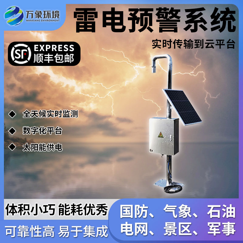
The lightning early warning system is a fully digital electric field detection and lightning early warning platform. Its core electric field detection structure is based on the principle of charge induction and developed using MEMS (microelectromechanical systems) technology. It has no motors and other easily wearable movable mechanical parts, and has small size and low power consumption. , high reliability, easy integration and other outstanding advantages. The system uses electric field differentiation combined with thresholds to optimize the lightning warning algorithm. Compared with the conventional threshold method, it has a high probability of avoiding false alarm problems caused by human interference (rainy days/strong winds/snowy days/dust), etc., further improving the accuracy of early warnings. Accuracy. The lightning early warning system provides accurate warnings, is easy to network, and is easy to install. It is mainly oriented to the application needs of atmospheric electric field detection and lightning local short-term early warning in the fields of aerospace and national defense, meteorology, petroleum and petrochemicals, power grids, scenic spots, mines, oil depots, and military.
2. Product composition
1. Lightning early warning probe
2. Data processing host
3.Solar power supply system
4. Anti-direct lightning system
5. Surge system
6. Grounding system
7. Optional functions, temperature, humidity, lifting lightning rod
3. Product features
1. Users can connect the lightning warning system probe to the computer to achieve remote monitoring.
2. Through data analysis, make more accurate judgments on thundercloud electrostatic field intensity and polarity changes.
3. This system can be connected with the sound and light alarm system
4. The system software has complete network transmission functions; data transmission completely follows the network protocol
5. Equipped with central monitoring software, users can monitor and use it through a PC
4. Technical parameters
| Device name | Lightning warning system |
| Electric field measurement range | -30kV/m~30kV/m |
| resolution | 20V/m |
| Accuracy | Better than 5% |
| Detection distance (radius) | 15KM |
| Sensor weight | 3kg |
| gross weight | 50kg |
| input voltage | 24VDC/220VAC |
| Power consumption | 0.65W (sensor); 1.8W (system) |
| size | 300mm (sensor); 1.5m (bracket) |
| working temperature | -40℃~55℃(sensor); -20℃~55℃(controller) |
| Deployment location (indoor/outdoor) | outdoor |
| Whether to support rack deployment (indoor) | / |
| Shelf height | 1.5m (bracket) |
| Management interface type | RJ45, RVV |
| Supported management (control) functions | Level 3 early warning threshold setting and field coefficient setting |
| Number and type of data interfaces | 1 aviation socket, 1 network interface |
| Outbound data bandwidth requirements | 50Mbps |
| Outgoing data frequency | 1s |
| Outgoing data communication protocol | own agreement |
5. Installation precautions
1. Lightning warning probes should be installed on sunny days
2. The lightning warning probe should be installed outdoors where there is no obstruction and no obstructions around it.
3. It shall not be installed at the generator exhaust outlet, next to telephone poles or under high-voltage lines.
4. Under abnormal circumstances, when protruding from the ground, close to antenna poles or other equipment, the field strength and its test data may be interfered with
5. In wired mode, the wiring distance from the outdoor electric field meter probe to the indoor host is not recommended to exceed 100 meters.
6. Please consult our company for more details
7. If there are any parameter updates, we will not notify you. The right of technical explanation belongs to our company.
6. Installation steps
1. Take out the complete lightning warning system from the box
2. Fix the bracket to the designated installation position and secure it with bolts
3. Connect the lightning terminal tip on the top of the lightning rod to the ground wire. The other end of the ground wire is introduced from inside the bracket and out from the hole at the bottom of the bracket. After installing the ground electrode and other grounding devices, connect the lightning rod to the ground wire.
4. Introduce the wire of the atmospheric electric field meter probe from inside the bracket, lead it out from the hole in the middle of the bracket, and connect it to the main control box. There are three wires in the main control box. Connect them according to color and insulate them.
5. Fix the solar panel to the bracket and connect the solar cable to the lead power cable according to the color.
6. Install the control box in a suitable location in the control room, usually wall-mounted. Connect the alarm wire to the control box and connect it to the control box according to the color. Connect the 220V power supply to the circuit breaker
7. Lead a network cable and a control line from the front-end main control box according to the interface, and connect them to the control box in the control room. Connect the network cable and control line according to the interface.
8. Turn on the main control box switch and indoor control box switch power.
9. Turn on the computer and enter the main control box IP into the computer.
Product address:
http://www.qxhjjc.com/en/zidong/1318.html 


 Home
Home phone
phone Product Overview
 Contact Us